
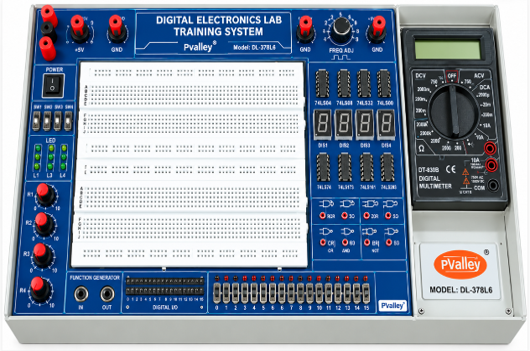
Brand: PValley
Model: DL-378L6
Country of Origin: China
Country of Assemble/ Manufacturer: Bangladesh
Technical Specification:
Solderless Breadboard: Interconnected nickel plated contact with 1680 tie-points
- DC Power Supply:
- Variable ±1.5VDC~ ±15VDC/500mA
- Fixed +5VDC/1A
- Fixed -5VDC/500mA
- Fixed +12V/500mA
- Minimum Sixteen (16) Bits Output LEDs
- Minimum Sixteen (16) Bits Data Input Switches
- Four (4) Slide Data Input Switches
- Two (2) Pulse Switches (with debounced circuit); outputs TTL and complement TTL
- Pulse Signal Generator (Variable):
- Frequency Range: 1Hz~10Hz; 10Hz~100Hz; 100Hz~1KHz; 1KHz~10KHz; 10KHz~100KHz; 100KHz~1MHz
- Output: TTL and variable amplitude output
- RC Configurable Timer Output from 1Hz
- AC Supply: 12VAC, 50Hz (with Overload Protection)
- Built-in Speaker (8 Ohms)
- Robust Mono-Board Design
- Intelligent Logic Probe with 7-Segment LED Indicator
- Built-in Digital Multimeter:
- Display: 3.5 digit LCD
- DC Voltage: 200 mV/2V/20V/200V/1000V
- DC Current: 2000μA/20mA/200mA/10A
- AC Voltage: 200V / 750V
- Resistance: 200Ω / 2KΩ / 20KΩ / 200KΩ / 2000KΩ
- Continuity Tester
- Transistor Tester
- Variable Resistor (Potentiometer):
- 1K-Ohm (0.25W); 3-output terminals
- 100K-Ohm (0.25W); 3-output terminals
- 1M-Ohm (0.25W); 3-output terminals
- Four (4) digits 7-segment LED display with BCD decoder drivers
- Dimension: 375mm x 200mm x 114mm(WxDxH)
- Input Supply: 240VAC/50Hz
- Mains ON/OFF switch with indicator & overload protection with fuse
TEACHING MODULE SPECIFICATION:
- BASIC LOGIC GATE MODULE – Model: MOD1:
- Overview & Introduction to logic & digital switches
- Basic logic gates experiments & characteristic: OR, AND, Inverter, NOR, NAND
- Boolean Algebra & Simplification of logic equation
- DeMorgan’s Theorem & Karnaugh Map simplification
- Introduction to TTL, CMOS, DTL, DL & RTL logic circuit
- Universal function for NAND and NOR gates
- Basic combinational circuit using AND, NAND, OR, NOR & NOT logic
- Circuit components:
- HEX inverter (NOT Gates): 4 sets
- 2 input OR Gate: 2 sets
- 2 input AND Gate: 2 sets
- 2 input NAND Gate: 4 sets
- 2 input NOR Gate: 4 sets
- 3 input OR Gate: 2 sets
- 3 input AND Gate: 2 sets
- 3 input NAND Gate: 2 sets
- 3 input NOR Gate: 2 sets
- 4 input OR Gate: 1 set
- 4 input AND Gate: 1 set
- 4 input NAND Gate: 1 set
- 4 input NOR Gate: 1 set
- EXCLUSIVE OR(XOR) & LINE ENCODER / DECODER – Model: MOD-2:
- Introduction to Exclusive OR(XOR) and XNOR gates
- XOR logic using NAND gates, NOT-AND-OR gates, NOT-NOR gates
- XNOR logic using NOT-NAND gates
- Dual input XOR circuit: 4 sets
- Dual input XNOR circuit: 2 sets
- Tri-state Inverter using 74xx40
- Tri-state buffer using 74Lxx41
- 4 to 16 Line Decoder using 74xx154
- 8 to 3 Priority Line Encoder using 74xx148
- FLIP FLOP MODULE – Model: MOD-3:
- Introduction to RS, Data, T & JK Flip Flop
- Clocked RS Flip Flop using NAND gates
- Clocked D Flip Flop with clear & preset
- Clocked JK Flip Flop with clear & preset
- Constructing T Flip Flop from JK Flip Flop
- Constructing D Flip Flop from JK Flip Flop
- Synchronous Binary counters (count up/down)
- Asynchronous Mode-N counters
- Asynchronous Binary counter
- BCD counter
- Shift registers using D Flip Flop
- D Flip Flop circuits with clock in, clear & preset: 4 sets
- JK Flip Flop circuits with clock in, clear & preset: 4 sets
- RS Flip Flop circuits: 3 sets
- Clocked RS Flip Flop circuit: 1 set
- COMBINATION LOGIC 1 – Model: DEM-2 & 3:
- Constructing NOR circuits using basic gates
- Constructing NAND circuits using basic gates
- Constructing XOR circuits using basic gates
- Comparator circuit using XOR(2X) and NOT(2X) gates
- Parity Generator/Checker using MSI 74xx280
- Gray code to Binary conversion using XOR(3X) gates
- Binary to Gray code conversion using XOR(3X) gates
- Half adder circuit using XOR(1X) & AND(1X) gates
- Full adder circuits using XOR(1X), AND(2X) & OR(1X) gates
- Half subtractor circuit XOR(1X), NOT(1X), AND(1X) gates
- Full subtractor circuit using XOR(2X), AND(2X), NOT(1X) & OR(1X) gates
- Four bit parallel adder using IC chip
- On board faults switches
- COMBINATION LOGIC 2 – Model: DEM-4:
- Basic 1 of 4 Decoder using NOT(2X) & AND(3X) gates
- BCD-Decimal decoder using 74xx42
- 7-Segment Decoder/Drivers using 74xx47
- Decimal to BCD Encoder using 74xx147
- Basic encoder using NAND(2X) & pull up resistors
- On board fault switches
MANUAL & ACCESSORIES:
- Operation / User Manual x 1
- Lab Experiment Manual (with answer) x 1
- Power Cord Cable x 1
- Connecting Lead x 1
- Spare Fuse X 2

Reviews
There are no reviews yet.