Brand: PValley
Model: PH-2124S06
Country of Origin: China
Assemble/Manufacturer: Bangladesh
Technical Features:
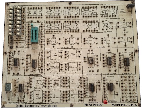
This integrated educational trainer module is designed and fabricated within the institution for Digital Electronics Laboratory. It demonstrates fundamental and advanced digital logic circuits, covering Logic Gates, Encoder-Decoder, Adders, Counters, Flip-Flops, and Registers.
All six modules are mounted vertically on a single framed panel for demonstration and student practical use.
Technical Specifications:
A. Logic Gate Module
- Parameter Specification
- Gates Included AND, NAND, OR, NOR, XOR, XNOR
- Additional Input Sensor Input (LDR/IR/Touch sensor)
- Input/Output Indicators LED indicators for logic levels
- IC Series TTL/CMOS (74 series ICs)
- Switch Push button
- Supply Voltage +5V DC regulated
- Function Demonstration of basic logic functions and truth tables
B. Encoder-Decoder Module
- Parameter Specification
- Encoders 4-to-2 line and 8-to-3 line encoder circuits
- Decoders 2-to-4 line and 3-to-8 line decoder circuits
- Display LED output display
- Switch Push button
- Supply +5V DC regulated
- Function Demonstration of coding and decoding logic operation
C. Adder Module
- Parameter Specification
- Circuits Included Half Adder, Full Adder, 3-bit Binary Adder, Serial Binary Adder
- Input/Output Indication LEDs and toggle switches
- Switch Push button
- Supply +5V DC regulated
- Function Demonstration of binary addition process using logic gates
D. Counter Module
- Parameter Specification
- Circuits Included Asynchronous Ripple Counter, Synchronous Counter, Johnson Counter, Ring Counter
- Clock Source On-board pulse generator with variable frequency
- Display 4-bit binary LED display
- Switch Push button
- Supply +5V DC regulated
- Function Demonstration of various counting operations and timing sequence
E. Flip-Flop Module
- Parameter Specification
- Types Included Bistable SR Latch, Level-Triggered Clocked SR Latch, Edge-Triggered SR Flip Flop, Level-Triggered JK Latch, Edge-Triggered JK Flip-Flop, D Flip-Flop, T Flip-Flop Clock Source Built-in clock pulse generator
- Indicators LEDs for Q and Q? outputs
- Switch Push button
- Supply +5V DC regulated
- Function Demonstration of bistable and sequential switching circuits
F. Register Module
- Parameter Specification
- Circuits Included Serial-in Serial-out (SISO), Serial-in Parallel-out (SIPO), Parallel-in Parallel-out (PIPO), Buffer Register
- Clock Input: On-board or external clock
- Indicators LED output display
- Switch Push button
- Supply +5V DC regulated
- Functional Demonstration of data storage and shifting operations
- G. General Construction
- Parameter Specification
- Frame Type Vertical metallic/aluminum frame with six detachable acrylic panels
- Panel Size Approx. 12 inch × 12 inch each
- Total Size Approx. 1000 mm × 600 mm × 200 mm
- Material PCB board/Acrylic sheet/Aluminum frame
- Finish Powder-coated frame, printed labels, and schematic diagrams
- Safety-fused DC line with over-voltage protection
- Supply 230V AC input with 5V regulated DC output supply
- Durability: Lab-grade, robust structure for frequent student use
Educational Objective:
- To provide hands-on training on digital logic circuits.
- To demonstrate combinational and sequential logic design.
- To enable understanding of binary operations, counting, and data storage.
- To help students design, test, and troubleshoot real digital systems.
Fabrication Details:
This trainer system will be locally fabricated using standard digital ICs (74-series TTL/CMOS), resistors, LEDs, switches, sensors, acrylic panels, and metal framing. All modules are interconnected and powered through a central 5V regulated power supply.
It will be considered under Raw Material Head (Lab Development Purpose)
Reviews
There are no reviews yet.