Brand: PValley
Model: AC-08CT
Country of Origin: China
Assemble/ Manufacturer: Bangladesh
Technical Specification:
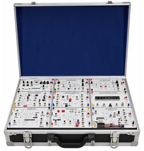
Analog Communication System or equivalent with all accessories & Modules
General characteristics
- Frequency range: 144~146 or 144~148 MHz
- PLL range: 130~170 MHz
- Modulation type: FM
- Channel setting step: 5, 10, 12.5, 20, 25, 50KHz
- Antenna impedance: 50 Ω
- Squelch sensitivity: 0.16 μVmax
- Audio output: 250mW
- Maximum offset: ±5KHz
- 1st IF signal: 21.8MHz
- 2nd IF signal: 455KHz
- Key-Pad function
- SQL: To eliminate the ZA noise on FM
- Volume: Power switch/ volume control
- TX/RX LED: Signal transmitter/ receiver indicator; red (transmitting) green (receiving)
- Channel: Channel selector
- S. socket: External MIC or speaker
- Function key
- PTT: Exchange transmitting and receiving function
List of Experiments
- Analog Communication System Introduction
- Hardset Reset
- Knowing SET Frequency
- Knowing 2 Function Keys Operation
- Knowing SET Key Function
- Microphone Amplifier
- Active Filter Circuit on the Microphone Amplifier
- Low Pass Filter Circuit on the Microphone Amplifier
- Measuring the frequency response of the passive high-pass filter
- Measuring the frequency response of the active low-pass filter
- Phase-Lock Loop (PLL) Circuits
- Observe the MB1504 Phase-Lock Detector Characteristics
- Measuring the Lock timing
- Measuring the LM565 Phase-Lock Circuit Characteristics
- Measuring the LM565 Phase-Lock Circuit Gain Factor
- Voltage Control Oscillator (VCO) Circuit
- Measuring the VCO gain of the transceiver
- Measuring the VCO Noise
- Measuring the VCO gain of the receiver
- VCO Circuit Simulation
- Power Amplifier
- Gain frequency response of the transceiver system
- Measuring the Automatic Gain Control Loop (AGC) of the power Amplifier
- RF Amplifier
- Measuring the linear frequency response of the RF Amplifier
- Measuring the non-linear frequency response of the RF Amplifier
- Band-pass filter circuit simulation
- Low noise amplifier circuit simulation
- RF amplifier circuit simulation
- Mixer and IF Circuit
- Measuring the Mixer exchange gain
- Measuring the gain of the crystal filter and the IF amplifier
- Mixer circuit simulation
- FM Demodulation Circuit
- Measuring the IF gain and interrupt loss of the FM Demodulation IC
- Measuring the Noise Strength of the FM Demodulation IC
- Measuring the Phase detector demodulation of the FM demodulation IC
- Audio Amplifier
- Measuring the power of the audio amplifier
- Measuring the noise ratio of the receiver circuit
- Measuring the frequency response of the audio amplifier
Accessories
- Power Supply
- Fixed DC power supply
- Output voltage: +5V, -5V, +12V, -12V
- Output current: +5V/3A, -5V/0.3A, +12V/1.5A, -12V/0.3A
- Output connector: 5 PIN DIN connector
- With output overload protection
- 1 pce Teacher’s guide
- Experiment manual: 1 pce
- VHF, FM transceiver: 1 set
Standard Accessories
- Power Cord
- Male to Male Banana Connector
- Experiment Manual and Instructor’s Manual
- 5 Days In-House Training
Protection:
Under voltage, Supply over voltage, Thermal, Short Circuit etc.
Warranty: 01 Years with services
Reviews
There are no reviews yet.